

| Data Acquisition Toolbox | |
How Fast Should a Signal Be Sampled?
Whenever a continuous signal is sampled, some information is lost. The key objective is to sample at a rate such that the signal of interest is well characterized and the amount of information lost is minimized.
If you sample at a rate that is too slow, then the signal is undersampled, and aliasing can occur. Aliasing can occur for both rapidly varying signals and slowly varying signals. For example, suppose you are measuring temperature once a minute. If your acquisition system is picking up a 60 Hz hum from an a.c power supply, then that hum will appear as constant noise level if you are sampling at 30 Hz.
Aliasing occurs when the sampled signal contains frequency components greater than one-half the sampling rate. The frequency components could originate from the signal of interest in which case you are undersampling and should increase the sampling rate. The frequency components could also originate from noise in which case you might need to condition the signal using a filter. The rule used to prevent aliasing is given by the Nyquist theorem, which states that
However, if your input signal is corrupted by noise, then aliasing can still occur.
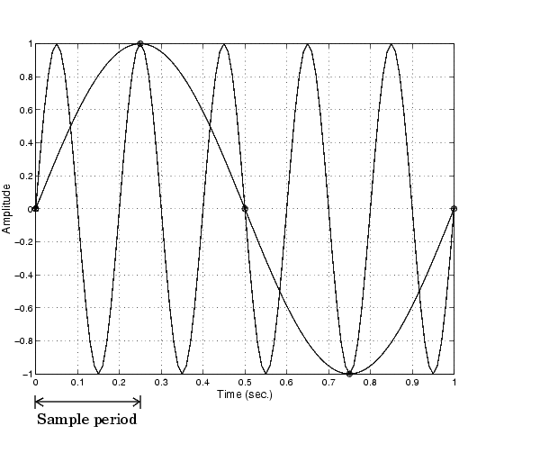
For example, suppose you configure your A/D converter to sample at a rate of 4 samples per second (4 S/s or 4 Hz), and the signal of interest is a 1 Hz sine wave. Because the signal frequency is one-fourth the sampling rate, then according to the Nyquist theorem, it should be completely characterized. However, if a 5 Hz sine wave is also present, then these two signals cannot be distinguished. In other words, the 1 Hz sine wave produces the same samples as the 5 Hz sine wave when the sampling rate is 4 S/s. This situation is shown below.
In a real-world data acquisition environment, you might need to condition the signal by filtering out the high frequency components.
Even though the samples appear to represent a sine wave with a frequency of one-fourth the sampling rate, the actual signal could be any sine wave with a frequency of
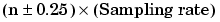
where n is zero or any positive integer. For this example, the actual signal could be at a frequency of 3 Hz, 5 Hz, 7 Hz, 9 Hz, and so on. The relationship 0.25 x (Sampling rate) is called the alias of a signal that may be at another frequency. In other words, aliasing occurs when one frequency assumes the identity of another frequency.
If you sample the input signal at least twice as fast as the highest frequency component, then that signal might be uniquely characterized, but this rate would not mimic the waveform very closely. As shown below, to get an accurate picture of the waveform, you need a sampling rate of roughly 10 to 20 times the highest frequency.
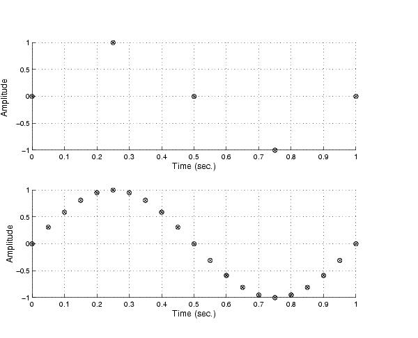
As shown in the top figure, the low sampling rate produces a sampled signal that appears to be a triangular waveform. As shown in the bottom figure, a higher fidelity sampled signal is produced when the sampling rate is higher. In the latter case, the sampled signal actually looks like a sine wave.
How Can Aliasing be Eliminated?
The primary considerations involved in antialiasing are the sampling rate of the A/D converter and the frequencies present in the sampled data. To eliminate aliasing, you must
| | Matching the Sensor Range and A/D Converter Range | Selected Bibliography | |