| Communications Blockset |
  |
CPM Demodulator Passband
Demodulate CPM-modulated data
Library
CPM, in Digital Passband sublibrary of Modulation
Description

The CPM Demodulator Passband block demodulates a signal that was modulated using continuous phase modulation. The input is a passband representation of the modulated signal. The M-ary number parameter, M, is the size of the input alphabet. M must have the form 2K for some positive integer K.
This block converts the input to an equivalent baseband representation using downconversion and then FIR decimation. The block then uses the baseband equivalent block, CPM Demodulator Baseband, for internal computations. The following parameters in this block are the same as those of the baseband equivalent block:
- M-ary number
- Output type
- Symbol set ordering
- Modulation index
- Frequency pulse shape
- Rolloff
- BT product
- Pulse length
- Symbol prehistory
- Traceback length
The input must be a sample-based scalar signal.
Parameters Specific to Passband Simulation
Passband simulation uses a carrier signal. The Carrier frequency and Carrier initial phase parameters specify the frequency and initial phase, respectively, of the carrier signal. The Input sample time parameter specifies the sample time of the input signal, while the Symbol period parameter equals the sample time of the output signal.
This block uses a baseband representation of the modulated signal as an intermediate signal during internal computations. The Baseband samples per symbol parameter indicates how many baseband samples correspond to each integer or binary word in the output.
The timing-related parameters must satisfy these relationships:
- Symbol period > (Carrier frequency)-1
- Symbol period must be an integer multiple of the product of Output sample time and Baseband samples per symbol.
- Baseband samples per symbol > 4
- Output sample time < [2*Carrier frequency + 2*Fmax)]-1
where Fmax is defined as follows:
Fmax = [Frequency separation * (M-ary number - 1) / 2] + 1 / Symbol period
The Carrier frequency parameter is typically much larger than the highest frequency of the baseband signal.
The CPM Demodulator Passband block creates a delay in signals that it processes. This delay is caused by FIR filters in the block, whose tap length depends on signal and simulation parameters.
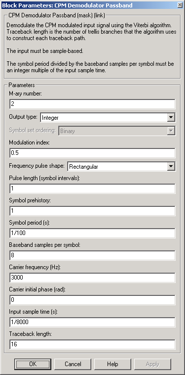
Dialog Box

- M-ary number
- The size of the alphabet.
- Output type
- Determines whether the output consists of integers or groups of bits.
- Symbol set ordering
- Determines how the block maps each integer to a group of output bits. This field is active only when Output type is set to Bit.
- Modulation index
- The number of half-revolutions of phase shift in the modulated signal after modulating the latest symbol of 1.
- Frequency pulse shape
- The type of pulse shaping that the corresponding modulator uses to smooth the phase transitions of the modulated signal.
- Main lobe pulse duration (symbol intervals)
- Number of symbol intervals of the largest lobe of the spectral raised cosine pulse. This field is active only when Frequency pulse shape is set to Spectral Raised Cosine.
- Rolloff
- The rolloff factor of the raised cosine filter. This field appears only when Frequency pulse shape is set to Spectral Raised Cosine.
- BT product
- The product of bandwidth and time. This field appears only when Frequency pulse shape is set to Gaussian.
- Pulse length (symbol intervals)
- The length of the frequency pulse shape.
- Symbol prehistory
- The data symbols used by the modulator before the start of the simulation.
- Symbol period (s)
- The symbol period, which equals the sample time of the output.
- Baseband samples per symbol
- The number of baseband samples that represent each modulated symbol, after the block converts the passband input to a baseband intermediary signal.
- Carrier frequency (Hz)
- The frequency of the carrier.
- Carrier initial phase (rad)
- The initial phase of the carrier in radians.
- Input sample time(s)
- The sample time of the input signal.
- Traceback length
- The number of trellis branches that the Viterbi Decoder block uses to construct each traceback path.
Pair Block
CPM Modulator Passband
See Also
CPM Demodulator Baseband, Viterbi Decoder
References
[1] Anderson, John B., Tor Aulin, and Carl-Erik Sundberg. Digital Phase
Modulation. New York: Plenum Press, 1986.
 | CPM Demodulator Baseband | | CPM Modulator Baseband |  |


