

| Communications Toolbox | |
Representing Analog Signals
To perform baseband modulation of an analog signal using this toolbox, start with a real message signal and a sampling rate Fs in hertz. For modulation techniques other than quadrature amplitude modulation (QAM), represent the signal using a vector x, the entries of which give the signal's values in time increments of 1/Fs. Baseband modulation (using a technique other than QAM) produces a complex vector.
For example, if t measures time in seconds, then the vector x below is the result of sampling a frequency-one sine wave 100 times per second for 2 seconds. The vector y represents the modulated signal. The output shows that y is complex.
Fs = 100; % Sampling rate is 100 samples per second.
t = [0:1/Fs:2]'; % Sampling times for 2 seconds
x = sin(2*pi*t); % Representation of the signal
y = amodce(x,Fs,'pm'); % Modulate x to produce y.
whos
  Name      Size           Bytes  Class

  Fs        1x1                8  double array
  t       201x1             1608  double array
  x       201x1             1608  double array
  y       201x1             3216  double array (complex)

Grand total is 604 elements using 6440 bytes
Baseband Modulated Signals Defined
This section explains the connection between this complex vector y and the real signal that you might expect to get after modulating a real signal. If the modulated signal has the waveform

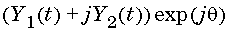
where fc is the carrier frequency and  is the carrier signal's initial phase, then a baseband simulation recognizes that this equals the real part of
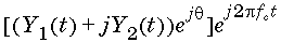
and models only the part inside the square brackets. Here j is the square root of -1. The complex vector y is a sampling of the complex signal
Changes for QAM
The case for quadrature amplitude modulation (QAM) is similar, except that the message signal has in-phase and quadrature components. Represent the signal using a matrix x that has an even number of columns. The odd-indexed columns represent in-phase components of the signal and the even-indexed columns represent quadrature components. If the message signal is a 2n-by-m matrix, then the modulated signal is an n-by-m matrix. As in the other methods, baseband modulation turns a real message signal into a complex modulated signal.
For example, the code below implements QAM on a set of sinusoidal input signals.
Fs = 100; % Sampling rate is 100 samples per second.
t = [0:1/Fs:2]'; % Sampling times
% Signal is a four column matrix.
% Each column models a sinusoidal signal, the frequencies
% of which are 1 Hz, 1.5 Hz, 2 Hz, 2.5 Hz respectively.
x = sin([2*pi*t,3*pi*t,4*pi*t,5*pi*t]);
y = amodce(x,Fs,'qam'); % Modulate x to produce y.
The output below shows the sizes and types of x and y.
whos
  Name      Size           Bytes  Class

  Fs        1x1                8  double array
  t       201x1             1608  double array
  x       201x4             6432  double array
  y       201x2             6432  double array (complex)

Grand total is 1408 elements using 14480 bytes
| | Modulation Terminology | Simple Analog Modulation Example | |