| CDMA Reference Blockset |
  |
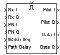
IS-95A Fwd Ch Rake Finger
Correlate the input signal over each Walsh code interval with the short PN code and Walsh code sequences
Library
IS-95A Mobile Station Receiver
Description
This block correlates the input signal over each Walsh code interval with the supplied PN and Walsh code sequences to estimate the channel and the data from the received signal. Using the known Walsh sequence for pilot symbols, this block estimates the in-phase and quadrature components of the channel. The input Walsh sequence, used to encode the data symbols, is used to estimate the in-phase and quadrature components of the received data.
The input signal is oversampled at eight times the chip rate, which is known as the tick rate. Initial PN phases are used to set the appropriate downsampling phase and timing for the delayed incoming multipath rays.
Inputs
- Enabler (on top)
- A positive value at the top port enables the block.
- Rx I
- Real vector representing the oversampled in-phase component of the input signal. The vector size is the Walsh Seq input vector size times the Oversampling rate parameter times the Input frame size parameter.
- Rx Q
- Real vector representing the oversampled quadrature component of the input signal. The vector size is the same as that of the Rx I input vector.
- PN I
- Real vector of bipolar data representing the in-phase component of the short PN code sequence. The vector size is the Walsh Seq input vector size times the Input frame size parameter.
- PN Q
- Real vector of bipolar data representing the quadrature component of the short PN code sequence. The vector size is the same as that of the PN Q input vector.
- Walsh Seq
- Real vector of bipolar data representing the Walsh code sequence. Its vector size is 2W, where W is the Walsh order parameter.
- Path Delay
- Integer scalar representing the rake finger PN phase, in samples.
Outputs
- Pilot I
- Real vector of size Input frame size representing the in-phase component of the channel estimate.
- Pilot Q
- Real vector of size Input frame size representing the quadrature component of the channel estimate.
- Data I
- Real vector of size Input frame size representing the in-phase component of the output data symbol.
- Data Q
- Real vector of size Input frame size representing the quadrature component of the output data symbol.
Dialog Box
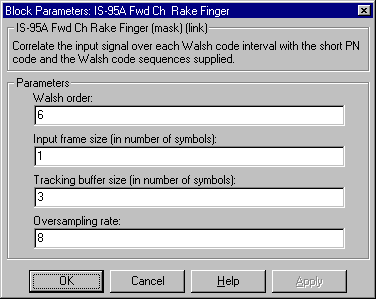
Parameters
- Walsh order
- Integer scalar that specifies the order of the Walsh code used to encode each data symbol. The default value, 6, corresponds to a Walsh code length of 64.
- Input frame size (in number of symbols)
- Integer scalar that specifies the number of symbols at the input of the rake correlator.
- Tracking buffer size (in number of symbols)
- Integer scalar that specifies the size of the buffer (in number of symbols) used to correct for differences in path delays of the received multipath rays. The length of this buffer limits the maximum phase difference between the received rays.
- Oversampling rate
- Integer scalar that specifies the number of samples per chip.
See Also
IS-95A Fwd Ch Detector
Specification References
IS-95A 7.1.3.1.8, 7.1.3.1.9
J-STD-008 3.1.3.1.9, 3.1.3.1.10
| | IS-95A Fwd Ch Rake Demodulator | | IS-95A Fwd Ch Repeater/Derepeater | |