The fact that there are two kinds of electrical charge, with similar charges repelling each other and different charges attracting each other was discovered in the early serious studies about electricity, by Charles Du Fay, by 1733 [1], who named them "vitreous" (positive) and "resinous" (negative), because they were usually generated by friction with glass and with resinous materials. For many years the true nature of the two kinds of charge was discussed, with some researchers proposing that they were really two different substances, as Du Fay believed, and others proposing that they were excess or lack of a single substance. Benjamin Franklin [3] and William Watson [4] proposed that the "vitreous" charge was the excess case, and so named it "positive", with the "resinous" charge being the lack case, "negative". As the usual electricity generators of that time used frictioned glass, which produces "vitreous" electricity, the naming was natural. Eventually it was discovered that the truth was a mix of the two old theories, with two kinds of charge really existing but just one being easy to move and causing excess of lack. The nature of the negative charge, the "electrons", light discrete bodies that are part of the atoms that compose all matter, was discovered first, in 1897 by J. J. Thomson, with the nature of the positive charge, located in "protons" at the nuclei of atoms discovered some time after, between 1911 and 1920, by E. Rutherford. Only the electrons (and just some of them) are easy to transfer between bodies, and so Franklin and Watson committed an error in the notion of what is excess and what is lack that become permanent. "Positive" electricity is actually a lack of negative charge, and "negative" electricity an excess of negative charge. "Positive" current in solid conductors is composed of negative charge, the very light electrons, moving in the opposite direction, as the heavy positive protons don't move, being fixed in the atoms. In gases or liquids the positive charge may move too, with atoms becoming "ions", positive when they lose electrons and negative when extra electrons attach to them, but these move slowly because they are heavy and big. A spark in air is formed essentially just by moving negative charge.
The true nature of the electrical charge is, however, not important for the behavior of common electric circuits and devices, where the classical consideration of charge as a property that can have two polarities and varies continuously works perfectly well.
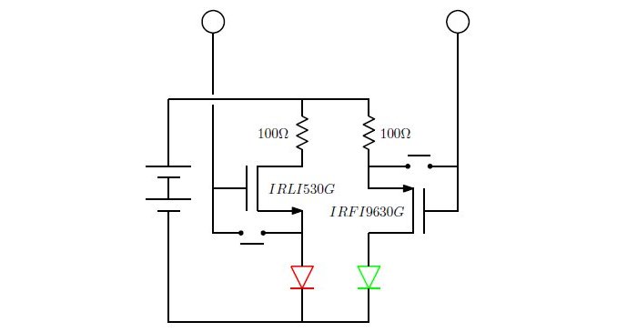
A simple electronic electroscope can be made with a high-impedance amplifier, as a JFET or a MOSFET, connected to an antenna and driving a LED of a current meter. A very simple version can be seen here. A more sofisticated version including two LEDs for indication of both polarities can be seen here. More complex versions go all the way to a precise electrostatic voltmeter. I have made some experiments after watching this video, that shows a double circuit using N and P MOSFETs as detectors, and two well-insulated antennas. The schematic that I used in the first version is shown below:
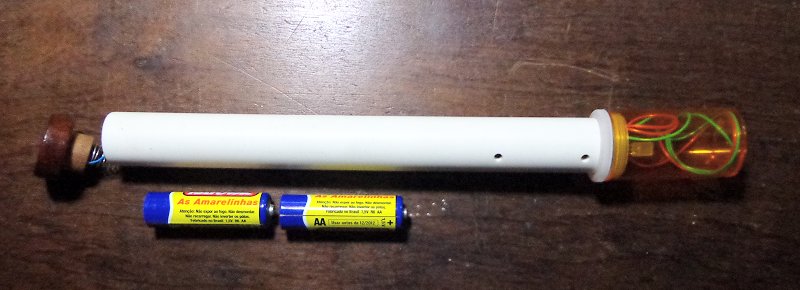
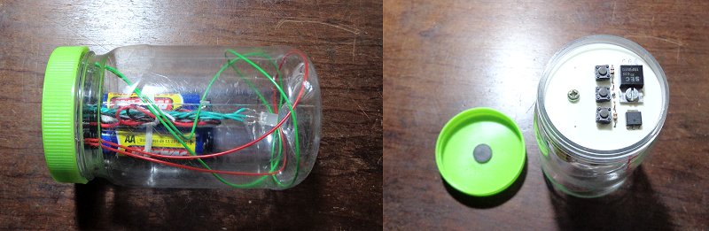
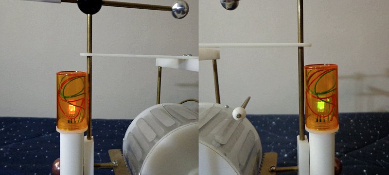
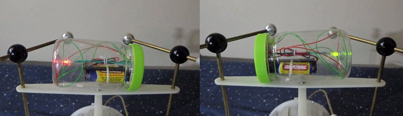
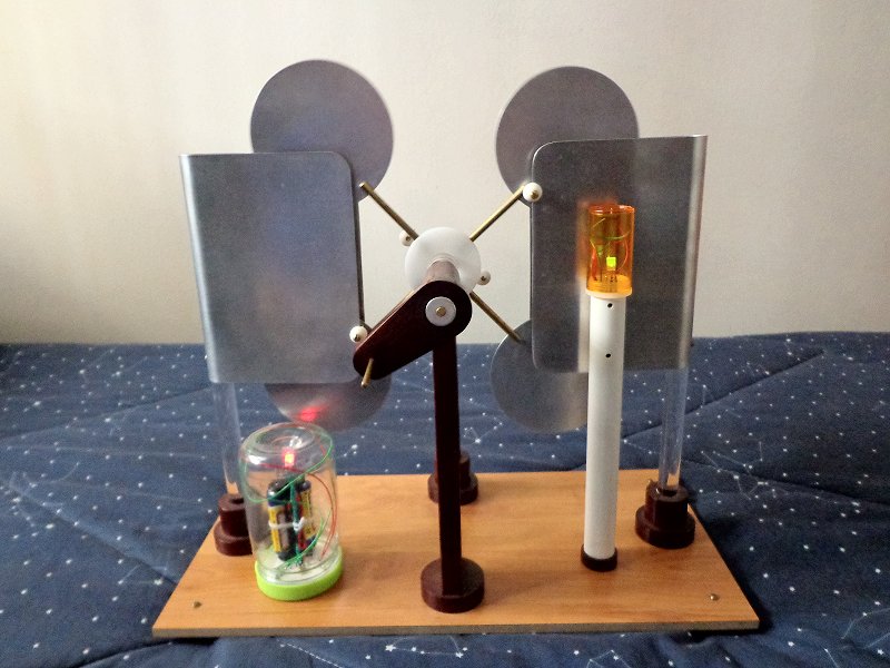
The MOSFETs are not critical. I just used some that I have at hand, taken from discarded circuit boards. Greater sensitivity is obtained with MOSFETs with smaller input capacitance, but the device works well even with power MOSFETs having several nF of input capacitance. To light LEDs just two 1.5 V batteries are enough. I used a two-colors LED, with a red LED to indicate positive charge, driven by the N-channel MOSFET, and a green LED indicating negative charge, driven by the P-channel MOSFET. A convenience of this circuit is that it almost does not consume any current when the LEDs are not on. The antennas are loops of insulated wire further protected inside a plastic box. This avoids destruction of the MOSFETs by direct discharges, and avoids, to some extent, charge transfer by corona, that would occur if the antennas were not insulated. Two small buttons are used to discharge the gates and reset the device to normal sensitivity. The pictures below show two versions of the device. In the first the batteries are mounted in a section of 3/4" PVC tube, with the circuits mounted in an acrylic plate at one end, and the antennas inside a small plastic box. In the second version everything is mounted inside a PET box, with an additional button that disconnects the batteries if the lid is untwisted a bit. The circuits are mounted in an acrylic disk which sits on a protuberance that these boxes have just below the mouth. This version is more practical, as the reset buttons are easily accessible. The MOSFETs are a small 2SK738 (N-channel, 30 V, 2A) and an IRF9610 (P-channel, -200 V, -1.8 A). The antenna for the P-channel device was made longer, in an attempt to equalize the sensitivities for both polarities.
Created: 5/5/2014
Last update: 11/5/2014
Developed and maintained by Antonio Carlos M. de
Queiroz
Return to Electrostatic Machines