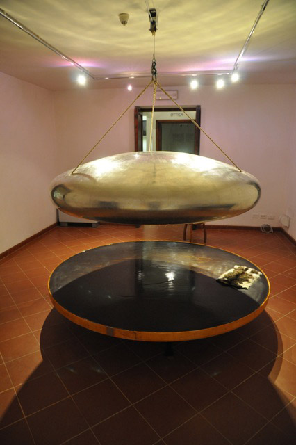
In 1775, Alessandro Volta [p110]
described a device that he named "Elettroforo Perpetuo". The idea was
already known from experiments of
Wilcke, in Sweden, some years before (1762), but Volta popularized the
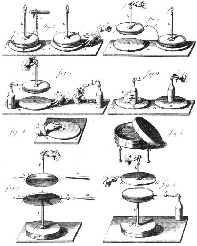
instrument in the most practical form. The figure above is from the
original paper, probably redrawn, and shows demonstration devices for
the electrophorus built by Volta. The basic device consists of a plate
C-C (fig. 1), made of metal or wood covered with metal foil, with
rounded edges, called the "shield", connected to an insulating handle
E,
originally made of glass varnished with shellac varnish. Below
there is a metallic "plate" A-A, covered with a layer of
insulating resin
B, making the "cake". The plate is actually not required, if the resin
block is placed over a partially conducting surface, as a wooden table,
and the operator is in contact with the ground. The plate is required
in the experiments in the two last pictures, however. A modern version
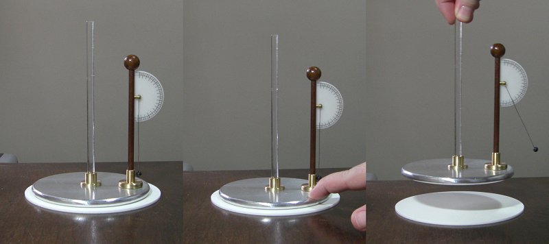
can use a plastic rod as the handle for the shield and a plastic plate
for the cake. See the pictures below.
If the shield is placed in
communication with the prime conductor of an electrostatic machine
(fig. 1), with the plate grounded, the capacitor formed by the shield
and the plate, with the resin as dielectric, is strongly charged. If
then the shield is touched, with the plate being touched at the same
time (or if the plate and the operator are grounded), the capacitor is
discharged by a strong spark, but a certain amount of charge, that
moved to the surface of the resin, is not removed. By rising the shield
it's noted that it is now charged with a polarity opposite to the
polarity at the resin surface, also contrary to the polarity of the
electrostatic machine used to charge the device. A similar effect can
be obtained by charging the resin B by frictioning it with a dry hand,
with a flanel, etc. (fig.5), placing then the shield over it
and
touching the shield and the plate, which is the most usual form of
charging the electrophorus. The resin can continue with an useful
charge for hours, even for several days, if the humidity of the air is
low. It's interesting to note that the charging method using an
electrostatic machine, although clearly mentioned by Volta
(and that works very well, see the video below),
is practically not mentioned in the posterior literature about the
electrophorus.
If the shield, after
touched, is rised from the resin, its electrical potential is greatly
increased.
Sparks can be drawn from it, for example to charge a Leyden jar
(fig. 3), that after a repetition for several cycles of the procedure
of placing the shield over the cake, touching it and the plate, and
rising it to touch the internal terminal of the jar, becomes strongly
charged. The discharge of the jar generates a spark more intense that
the electrophorus (fig. 3), due to the accumulated charge, but with the
same maximum voltage.
An electrophorus can be used to charge another with opposite polarity (fig. 2). The electrophorus at the right acts as the Leyden jar in fig. 3, and the electrophorus at left acts as the electrostatic machine in fig. 1. The wire K is just for convenience. The shield of the receiving electrophorus can be directly touched with the shield of the generating one after it is lifted from its cake. When the right electrophorus is well charged, after several cycles, it can be used to reinforce the charge in the first, with both exchanging roles. Thus, two electrophorus form an influence electrostatic machine, and become both more an more charged as the clycles are repeated. This form of charging only works reliably if the first electrophorus is highly charged, otherwise very little charge moves to the resin surface of the second. A better charging method, described by Lichtenberg, is to roll the border of the shield of the first electrophorus over the cake of the second (see a video below). Another form, attributed to Klinkoch, is to simply move the same shield between two cakes alternately, touching it at each time (I could not make this work in this way, but could if the shield border is rolled on the cakes before being placed over them and touched).
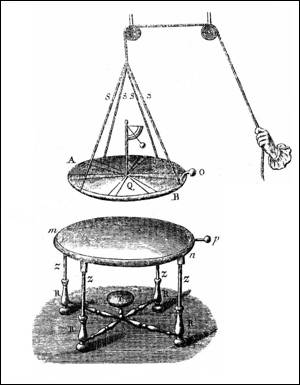
A Leyden jar can be used to reinforce the electrophorus charge (fig. 4). It is first charged as in fig. 3, and then placed over the cake, held by the base. Then, the jar is left there and, held by the internal terminal, moved over the cake surface. The procedure causes the partial discharge of the jar, with charge that was at its external armature being transferred to the cake surface. It's also possible to leave the shield over the cake when the jar is placed over the assembly, what is analogous to the procedure in fig.2, but using the jar instead of the electrophorus at the left. It's then enough to touch the button of the jar to cause the discharge, but this procedure requires more charge in the jar to be effective.See the comments by Ingenhousz about these reinforcement methods here (Philosophical Transactions, Vol. 68, p. 1028, 1778).
In fig. 7, the lower plate is mounted
over an insulating base, formed by a varnished glass rod E and a wooden
base P-P. The base, in the original paper, is a box where the other
devices can be stored
(fig. 6), and that can also be insulated by insulating feet and used as
an insulated platform, for example for the electrization of people.
Points N are mounted in holes in the shield and in the plate, a sphere
Q is mounted on the plate, and grounded points M are positioned as
shown. The electrophorus is then charged and the shield is rised to the
position shown. By observing the assembly in the dark, luminous
discharges (corona) are observed at the points.
In the picture, the shield is positive and the plate negative. Positive
corona (a plume) is observed in the point connected to the shield and
in the grounded point close to the sphere in the plate, and negative
corona (a luminous point)
is observed in the two other points. With the electrophorus charged
with opposite polarity, the corona appearances are inverted. This
experiment requires a large electrophorus to be clearly observable.
In fig. 8, the assembly is mounted
upside-down, and a Leyden jar, with the external armature grounded and
the internal terminal placed close to the ball connected to the shield,
is charged by sparks when the cake is rised after the charge of the
electrophorus. A spark can also be taken from the rised plate.
Created: 18 June 2012
Developed and maintained by Antonio
Carlos M. de Queiroz.
Return to Electrostatic Machines