I. Introduction
The interest in programs of energy conservation has been responsible for renewed attention to systems such as windmills, batteries, photovoltaic arrays, etc. These systems have the merit of generating energy without pollution and then they are called "clean" or "green" energy sources. On the other hand, the increasing power demand in most of the consumer centers has forced the planning engineers to look for new solutions to improve the capability of electrical utility systems.
Historically, photovoltaic systems have been used as powers supply only for special loads such as communication satellites. The continuous advances in the area of semiconductor materials led to the development of commercial PV cells with competitive cost, as compared with conventional generating systems. As a result, PV cells are now prominent as an alternative energy source.
The high hydroelectric potentials in Brazil make its electric utility system very special. The use of PV cells in residential and industrial applications can be a way for the consumer to purchase less energy from the utility system, therefore, saving the hydraulic energy. In this case, the hydraulic energy kept in the dams can be used at night, this means that the dam operates as an energy storage system. Solar cells can also be strategically connected to electric utility transmission and distribution systems.
In spite of a very attractive alternative with a reasonable price, the feeding of energy generated by a PV cell into an existing ac grid poses some problems to the control of the converters that connect the two systems. This is especially true if the ac system cannot supply reactive power and absorb harmonic currents.
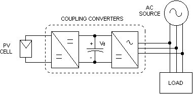
Figure 1 shows the schematic diagram of the system to be analyzed. The dc-dc converter drains the energy from the photovoltaic array and feeds the DC link capacitor with a maximum power point tracking (MPPT) control. This kind of converter is already well described in the literature [1] and will not be treated in this paper.

II. The Proposed System
Figure 2 shows a schematic diagram of a utility connection of PV cell through pwm voltage source inverter and its control. In this figure, each ideal switch represents a semiconductor device (IGBT) with a reverse diode in anti-parallel. Here, the proposed dc-ac converter uses a histeresys current control. Thus, the inverter output currents can track their references i*ca, i*cb and i*cc with a very small amplitude error or phase delay.
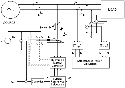
The accuracy of this tracking process is constrained by the maximum allowable switching frequency of the converter power switches, by the value of the dc voltage and by the converter output inductance. These problems will not be considered in this paper.
Now, assuming that the power variation frequency of the photovoltaic array is very small when compared with the ac network frequency, it will be considered that the PV cell current flowing into the dc link is nearly constant (ipv). Thus, in the following analysis the output of the dc-dc converter shown in Fig. 1 will be modeled as a constant current source.
If no energy is transferred from the dc link to the ac system, the average voltage across the dc link capacitor (vd) will increase linearly. However, an adequate control strategy, which permits that the energy delivered by the dc-dc converter to the dc link capacitor is transferred to the ac utility system, will be proposed.
A. The Converter Control Algorithm
A better understanding of the control strategy for the three-phase dc-ac converter can be achieved if the instantaneous power definitions introduced by Akagi et al. [2] are applied. That is:
where,
The symbols (-) and (~) in (1) denote respectively the average and oscillatory components of the corresponding quantities. The voltages and currents in (1) are obtained through a-b-0 transformation shown in the Appendix.
In a balanced three-phase system with linear loads, the instantaneous real power p and imaginary power q are constant and equal to the three-phase conventional active power P3f and reactive power Q3f [3], respectively. Then, for a given real and imaginary instantaneous power, the inverter control strategy consists in synthesizing output currents that the references in a-b coordinates are given by:
If only active power is to be injected in the grid:
The value of p* should be equal to the real power supplied by the PV cell to the dc link. From (2), the three-phase reference currents can be obtained by an inverse a-b-0 transformation.
On the basis of the theory presented it is possible to transfer the energy generated by the PV cells to the three-phase ac system controlling the instantaneous real power reference p*.
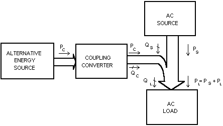
As, it can be seen in Fig. 3, if the ac load is absorbing an active power (PL) and reactive power (QL) and no power is supplied by the coupling converter the ac source reactive power and the active power will be equal to the powers in the load. Presumably, the power factor will be within the allowed limits. However, if the coupling converter starts to inject active power only, clearly the active power supplied by the ac source will decrease and the reactive power will be the same as before. In this condition, the power factor of the ac source will deteriorate. To solve this problem, the coupling converter should also supply or absorb active power and reactive power simultaneously.
Then a variable reactive power reference q* should be
included in the inverter control. Thus, the ac source can operate at the
allowed or unity power factor. That is, if q* is made equal to QL,
the source power factor can be kept equal to unity under different load
conditions.
III. The DC Capacitor Voltage Control
Assuming that there is no battery storage system connected at the dc link, the total energy delivered by the PV cells may overcharge the dc capacitor. As shown in the previous section, this energy should be injected into the ac system by controlling appropriately the signal p*. Neglecting the switching harmonics frequencies on the inverter output currents we can consider pc = p* and the following balance energy can be written for the capacitor Cd , Fig. 2:
 (4)
(4)where,
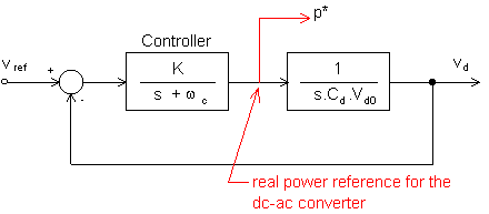
As shown above the energy stored in the dc capacitor is given by the integral of the instantaneous difference of powers pCd = (vd.ipv - pc). Then considering a small signal model and applying the Laplace transformation in (4) we obtained:
where,
Figure 4 shows a block diagram of a proposed scheme to transfer the energy from the dc capacitor to the ac system controlling the voltage across the dc capacitor. The capacitor voltage (vd) is measured and compared with a reference voltage (vref). The output of the controller is the real power pc = p*. Based on (4), the controller was chosen as a simple proportional gain K and a low pass filter to filter-out the switching harmonics present in the dc capacitor voltage.
IV. Digital Simulation
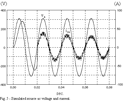
Digital simulation results obtained from PSPICE program are presented in Fig. 5 and 6. The gain K and the cut-off frequency of the controller shown in Fig. 4 were chosen equal to 20 and 0.5 (rad/s), respectively. The coupling converter (dc-dc converter and the inverter) operation begins at t = 20ms.
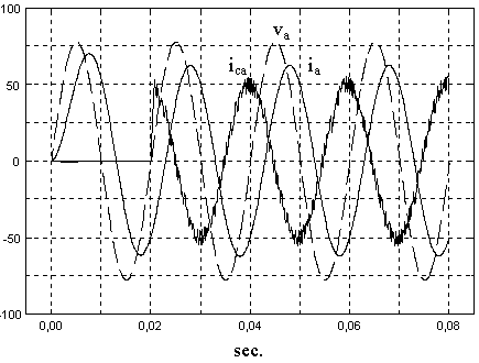
The reference of dc link voltage is equal to 750V and the line-to-neutral voltage at the three-phase side is 220V (rms). The power injected by the converter corresponds to approximately 20% of the load active and 100% of the load reactive (inductive) power. The three-phase voltages and currents are shown only for phase a. Similar wave-forms can be plotted for phases b and c.
From Fig. 5, it can be seen that immediately after the converter begins to operate, the source currents get in phase to each line-to-neutral voltage, making the power factor turn equal to unity. This happens due to the reactive power compensation made by the coupling converter. In Fig. 5, also, it can be seen that the source current decreases to approximately half of its previous value, due to the active and reactive power injection by the coupling converter.
Figure 6 shows the simulated load and converter currents,
as well as the converter voltage. Since the converter current is advanced
with respect to the phase voltage it is a capacitive current.
V. Experimental Results
A small scale prototype using IGBT has been built in the laboratory to confirm the theory. In this experimental system the pwm-vsi converter was connected directly to the utility system without any load. Table 1 shows the prototype parameters.
Table 1 - System parameters
| ac phase voltage | 55 V (rms) |
| ac line current (max.) | 3.3 A (rms) |
| average dc voltage | 120 V (dc) |
| average switching frequency | 3 kHz |
| dc link capacitor | 120 mF |
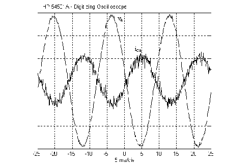
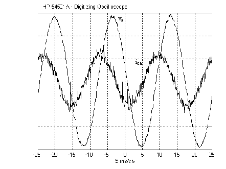
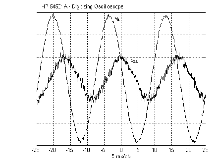
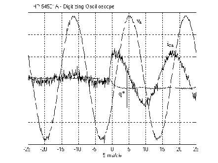
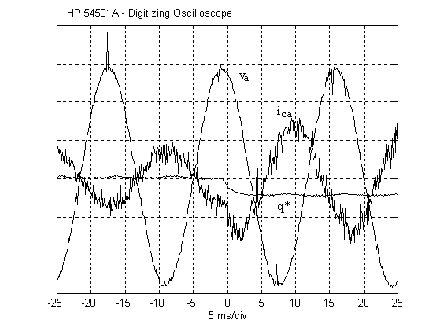
Figure 7 shows the experimental steady state phase voltage and line current for one phase of grid connected pwm-vsi supplying active power to the utility ac system. Fig. 8 and 9 show the pwm-vsi synthesizing respectively a capacitive and inductive current in steady state operation. The three-phase currents synthesized by the pwm-vsi present some switching harmonics. These harmonics will have to be filtered out in the case of industrial applications. However, due to the high frequency switching this filtering can be done by a small filter.
Figure 10 shows a transient response of the grid connected converter when the reactive power reference value (q*) is changed from zero to -250 VAr in one step. The pwm-vsi capacitive current is changed almost instantaneously.
In Fig. 11 the pwm-vsi is transferring active power from the dc link to the ac system. In this test, the reactive power reference value (q*) is changed in one step from zero to a capacitive value. During the time after the step the converter current increases its magnitude and becomes advanced with respect to the phase voltage.
VI. Design considerations
If the converter is supplying all the reactive power demanded by the load, its output currents are expected to be higher than they would be in the case when only active power is injected. This calls for higher output apparent power ratings. However, if a lower source power factor is admissible, the converter output ratings and therefore its cost can be reduced. The proposed control strategy is supposed to be capable of generating any output imaginary power, that is, the source power factor may be set at any desired value. In case of choosing a particular value for the source power factor, the imaginary power reference q* should no longer be set to qload, but to the following value [4]:
where, f* is the source desired reference displacement angle (cosf* is the reference power factor).
Therefore, neglecting the harmonics, the apparent power of the converter should be:
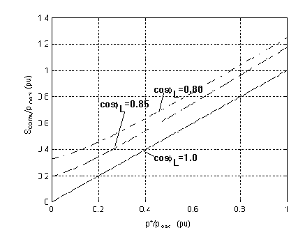
Figure 12 shows how the converter output apparent power can be determined for three different load power factor and considering the capacity of the solar cell (p*). In this figure the maximum admissible source power factor was considered equal to 0.92 (f* @ 23° @ 0.40 rad). From this figure it is possible to see that if the load power factor is equal to unity the converter will have the same rating as its active power p*. However, if the load power factor is, for instance, equal to 0.80 and p* is 0.4 (in pu) the converter rating will have to be 0.63 (pu).
If the load currents contain harmonics, the converter
can also supply them, with slight modifications in the control strategy.
In this case, the converter will also operate as an active power filter,
making the three-phase source currents nearly sinusoidal. The small high-frequency
oscillations produced by the converter on the three-phase source currents
can be easily filtered out by a small passive filter.
VII. Conclusions
A novel control strategy for grid-connected dc-ac converters with power factor control was presented. The strategy is based on the instantaneous real and imaginary power concepts, which are commonly used in the field of active power filter control. The effectiveness of the proposed scheme was evaluated through digital simulations. Additionally, guidelines for the determination of converter power ratings were given. It is important to point out that the control system proposed here can be used in many different kinds of alternative power source.
As a final remark, it should be said that the additional functions of power factor correction and harmonic filtering can help to improve the cost-effectiveness of a system primarily intended for active power feeding from an alternative energy source into an existing three-phase ac system.
Another interesting point is that the change in power factor regulations in Brazil may force some industry to use some kind of active power factor compensation. In this case, if this compensation is done by an active shunt compensator [5], the high cost of this system can be partly paid by connecting also a PV system in its dc side.
VIII. Acknowledgments
The authors would like to acknowledge the important support
received from CNPq and GTZ.
IX. References
[1] Z. Sallameh and D. Taylor, "Step-up Maximum Power Point Tracking for Photovoltaic Arrays", Solar Energy, vol. 44, No. 1, p. 57, 1990.
[2] H. Akagi, H., Y. Kanazawa and A. Nabae, "Instantaneous Reactive Power Compensators Comprising Switching Devices Without Energy Storage Components", IEEE Transactions on Industry Applications, Vol. IA-20, No. 3, p. 625, 1984.
[3] E. H. Watanabe, R. M. Stephan and M. Aredes, "New Concepts of Instantaneous Active Power in Electrical Systems with Generic Loads", IEEE Transaction on Power Delivery, Vol. 8, No. 2, April, 1993.
[4] V.V. Tavares, "Concepção do Controle de Conversor CC-CA para Aproveitamento de Energia Solar", Graduation Thesis, EE-UFRJ (Federal University of Rio de Janeiro), March, 1994 (in Portuguese).
[5] P. G. Barbosa, I. Misaka and E. H. Watanabe, "Advanced
Shunt Active Var Compensator", II COBEP, Proc., Uberlândia,
Dec. , 1993.
The (a-b-c)®(a-b-0) transformation and its inverse transformation for the three-phase voltages are given by:
 (A.1)
(A.1)and,
 (A.2)
(A.2)Similar expressions can be defined for the currents.