 Along with the
old Van de Graaff generator that I
restored for the exposition at the
Espaço COPPE there was another terminal with almost the same
size. I decided to make a new machine to use it, experimenting with
some possibilities in the construction of these machines. I found also
a big ceramic insulator that would make an impressive machine if used
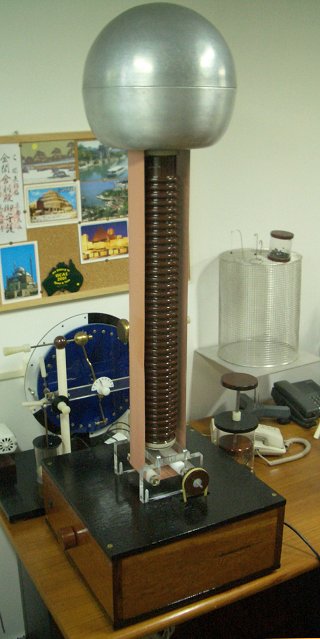
as central support for a machine with external belt. The machine was
completed in April 2007. The insulator is quite thick, and so the top
and bottom rollers would have to be large if made as simple cylindric
rollers. To save space and materials I decided to use four rollers
instead, two below and two above, routing the belt around the
insulator. Three of the rollers are made of nylon and one, the
excitator roller, of Teflon. Nylon is a relatively bad insulator, and
doesn't get strongly electrified by friction with the belt. The base of
the machine is a wood box made with panels fixed with brass screws. The
upper and lower panels are plywood, dyed dark brown. Inside the box is
installed the motor, a common sewing machine motor.mounted on a wood
block, fixed to the bottom of the box. The speed of the motor is
controlled by a 300 W lamp dimmer installed on the front panel,
directly replacing the resistive speed controller which came with the
motor. The box also has an on-off switch, a socket for the power cord
(computer type), and a ground connector connected to the ground wire of
the power cord.
Along with the
old Van de Graaff generator that I
restored for the exposition at the
Espaço COPPE there was another terminal with almost the same
size. I decided to make a new machine to use it, experimenting with
some possibilities in the construction of these machines. I found also
a big ceramic insulator that would make an impressive machine if used
as central support for a machine with external belt. The machine was
completed in April 2007. The insulator is quite thick, and so the top
and bottom rollers would have to be large if made as simple cylindric
rollers. To save space and materials I decided to use four rollers
instead, two below and two above, routing the belt around the
insulator. Three of the rollers are made of nylon and one, the
excitator roller, of Teflon. Nylon is a relatively bad insulator, and
doesn't get strongly electrified by friction with the belt. The base of
the machine is a wood box made with panels fixed with brass screws. The
upper and lower panels are plywood, dyed dark brown. Inside the box is
installed the motor, a common sewing machine motor.mounted on a wood
block, fixed to the bottom of the box. The speed of the motor is
controlled by a 300 W lamp dimmer installed on the front panel,
directly replacing the resistive speed controller which came with the
motor. The box also has an on-off switch, a socket for the power cord
(computer type), and a ground connector connected to the ground wire of
the power cord. 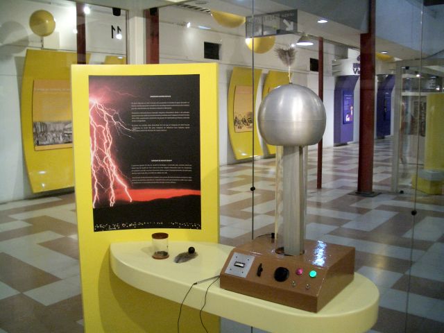
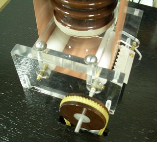 The lower
assembly is made with 1.5 cm acrylic plate, in three blocks with the
same dimensions. Two rollers with metal axles are supported by brass
tubes inserted in
the blocks. The motor powers one of them trough a wood pulley with
nylon center. A grounded comb made with serrated aluminum foil is
placed close to the roller driven by the motor, from where the belt
goes up. The ceramic insulator is hollow, and has inside it a PVC tube
that fits tightly. A wood cylinder screwed to the upper acrylic block
enters the tube and holds it in place by gravity (it is heavy). A
rubber ring below the insulator avoids scratches in the acrylic and
excessive vibration.
The lower
assembly is made with 1.5 cm acrylic plate, in three blocks with the
same dimensions. Two rollers with metal axles are supported by brass
tubes inserted in
the blocks. The motor powers one of them trough a wood pulley with
nylon center. A grounded comb made with serrated aluminum foil is
placed close to the roller driven by the motor, from where the belt
goes up. The ceramic insulator is hollow, and has inside it a PVC tube
that fits tightly. A wood cylinder screwed to the upper acrylic block
enters the tube and holds it in place by gravity (it is heavy). A
rubber ring below the insulator avoids scratches in the acrylic and
excessive vibration. 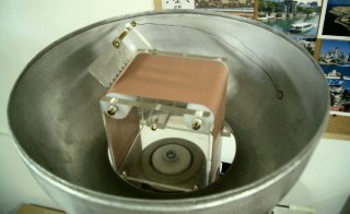 The upper
assembly is made with 6 mm acrylic plate, and holds the two other
rollers in the same way used below. A comb connected to the terminal is
placed close to one of the rollers, where the belt goes down. The two
square lateral panels and a disk with cutouts
for the belt below were dimensioned to hold the lower part of the
terminal in place. The assembly is fixed by a screw to a Teflon block
that seals the top of the PVC tube inserted in the ceramic insulator.
This minimizes possible losses trough the interior of the tube.
The upper
assembly is made with 6 mm acrylic plate, and holds the two other
rollers in the same way used below. A comb connected to the terminal is
placed close to one of the rollers, where the belt goes down. The two
square lateral panels and a disk with cutouts
for the belt below were dimensioned to hold the lower part of the
terminal in place. The assembly is fixed by a screw to a Teflon block
that seals the top of the PVC tube inserted in the ceramic insulator.
This minimizes possible losses trough the interior of the tube.
The belt was made of rubber, for medical use (brand Cirurgiabrasil), cut 7 cm wide.
The excitation Teflon roller is placed below, as the driving roller. The roller gets charged negatively by rolling friction with the belt, and the belt then goes up with positive charge that comes trough the grounded comb. The terminal is positive.
The machine gets easily strongly charged, even without the terminal. The positive charge results in a crackling sound and corona (visible in the dark) below the terminal, exactly as happens in my other positive Van de Graaff generator. It's not easy to draw solid sparks from a positive terminal. Only negative corona is obtained if a grounded object is brought near (~30 cm) from the terminal. The electric field can be easily felt two meters away, pulling at hairs and ball electrometers.
Originally, the machine was planned to have a negative terminal, with the excitation roller placed inside the terminal. This, however, resulted in poor and erratic performance, because most of the charge deposited in the belt by the upper comb was lost where the belt passes close to the terminal aperture while going down. This is a fundamental limitation of this kind of construction. If the belt is enclosed in a tube and passes at significant distance from the terminal aperture, there is not so much loss, and a machine with excitation inside the terminal works, as in the machine cited at the beginning of the page, built in this way. The Nylon roller in front of the lower comb below was not sufficiently insulated to operate as a good current doubler too (The idea of the current doubler in this case is that as the positively charged belt going down touches the roller it transfers some positive charge to it, what attracts more negative charge from the grounded comb than a neutral roller would attract if just discharging the positive belt). The doubler could be made to work if the grounded comb was replaced by a brush made with carbon fiber, touching the belt in front of the roller. But even with this the performance was erratical. I tried to cover the doubler roller with adhesive aluminum tape, but this resulted in aluminum dust being transferred to the belt. With the inverted connection used, there is no loss and the machine performs consistently. The doubler inside the terminal is better insulated, but most of its effect is lost when the belt crosses the terminal aperture. It's uncertain if it is working. The machine still has some mechanical problems. The simple bearings used present excessive friction, what requires strong tension in the belt to avoid it slipping at the low friction Teflon driving roller, and should be replaced by ball bearings. The motor mounted in the lower panel of the box with the pulley driving the belt mounted in the upper panel results in excessive vibration and noise. The motor should be transferred to the upper panel to minimize this.. The characteristics of the ceramic insulator are being observed. It is a good insulator when dry, but maybe not so good as a plastic insulator would be. It has the usual ringed outer surface, but it is hollow, and the inner surface is smooth, an invitation to tracking. The effect of the sealed PVC tube inserted in the interior of the insulator is also being evaluated. After some time in operation, if the tube is removed it is observed to be strongly charged. If this is good or bad for the insulation of the machine is something to verify. The insulator can be removed, with the internal PVC tube left supporting the terminal (not so firmly), what allows a comparison of the insulation in both cases. So far no significant difference was observed.
After 6 months of operation, the belt started to develop small holes, specially at the joint. It was replaced by a Thera-Band gray belt, that appears to work almost as well as the other.
After almost 2 years, I tried to increase the friction between the Teflon roller and the belt, to reduce slippage, by scratching the surface of the roller, and cut a section of the belt to increase its tension. This at first worked well, but after a few weeks many small holes appeared on the belt. I think that the cause was a combination of the scratched roller with the increased tension, on an already worn belt. I changed then the mechanism on the lower assembly, adding a pair of pulleys linking the two rollers trough a rubber cord. I also polished the rollers again. The modified assembly solved the slippage problem.
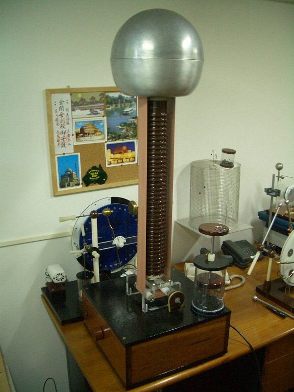
A big picture. The machine is charged. Note the ball electrometers and the hailstorm boxes.