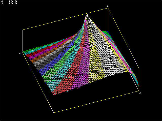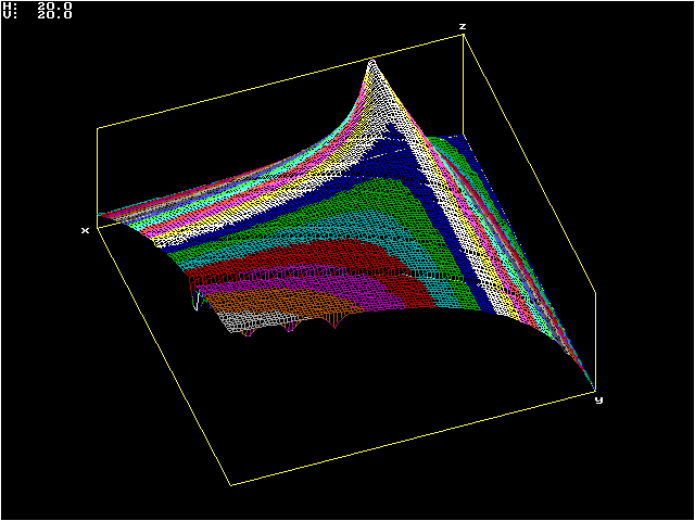
The next plot shows the effect of
varying C1,
between 0.01 F and 4 F, while k
varies between 0.05 and
0.9. It can be observed that larger C1
always result in larger output
voltage. With low k, this
happens for just a small increase in C1
before detuning reduces the effect, but after a certain value of k, increasing C1 increases the voltage
continuously, with it tending to a value proportional to k for large C1. The output voltage
is always greater than the normal with C1 increased after k =
0.5, tending to twice the normal value for large C1 and k = 1. This is, however, of little
practical interest, since the system loses efficiency, with just a
fraction of the initial energy in C1
being transferred to C2.
Note the trenches again, with depths that vary periodically.


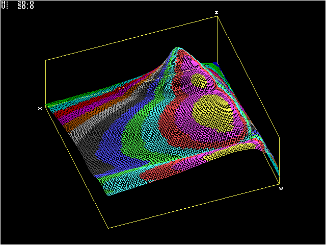
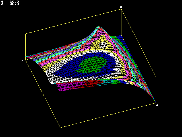
The two plots below illustrate the
effect of losses. In this case a resistance of 20 Ohms in parallel with
the output capacitance, corresponding to a quality factor Q = 20 for the secondary circuit.
The variation of L1
just produces more clearly defined peaks, practically at the same
places.

The variation of C1 shows maxima skewed in the direction of larger C1, and reduction in the output voltage for large C1. (further increase in C1 results again in the maximum output voltage proportional to the coupling). The trenches are smoother in these lossy cases.

For a regular Tesla coil, only the range with low k is of interest, and there the effects of changing L1 or C1 are similar. But for energy conversion devices operating with high coupling, the increase in the output voltage caused by increasing C1 may be of interest.
Thanks to Terry Fritz for the idea of making this kind of plot. These were made with a program that I wrote, but the same thing can be done with Terry's Scantesla program (see the archives of the Tesla list) and a suitable plotting program.

The variation of C1 shows maxima skewed in the direction of larger C1, and reduction in the output voltage for large C1. (further increase in C1 results again in the maximum output voltage proportional to the coupling). The trenches are smoother in these lossy cases.

For a regular Tesla coil, only the range with low k is of interest, and there the effects of changing L1 or C1 are similar. But for energy conversion devices operating with high coupling, the increase in the output voltage caused by increasing C1 may be of interest.
Thanks to Terry Fritz for the idea of making this kind of plot. These were made with a program that I wrote, but the same thing can be done with Terry's Scantesla program (see the archives of the Tesla list) and a suitable plotting program.