In 2008 I made some experiments with
high-voltage power supplies made with flyback transformers, using parts
salvaged from discarded monitors. I built a series of power supplies
that can
be
used for further experiments with moderately high voltage, as powering
"lifters", charging Marx generators, providing excitation for Van de
Graaff generators, starting sectorless influence machines, powering
small Tesla coils, Jacob´s ladders, etc.
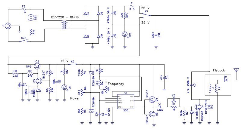
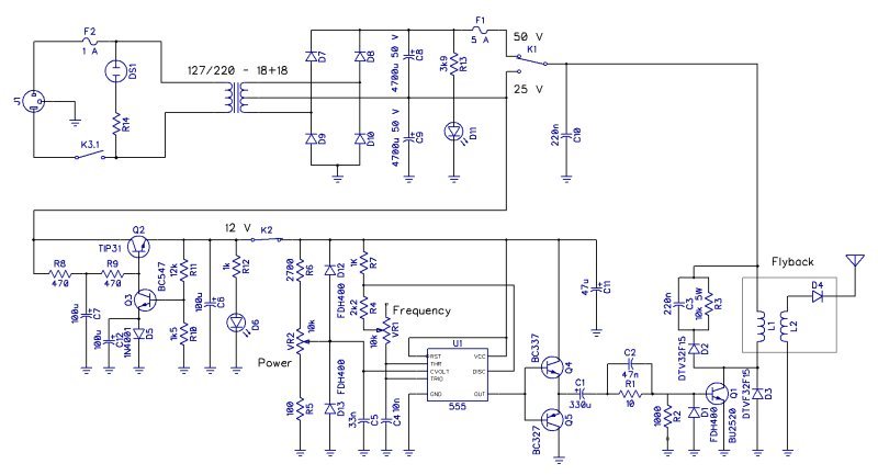
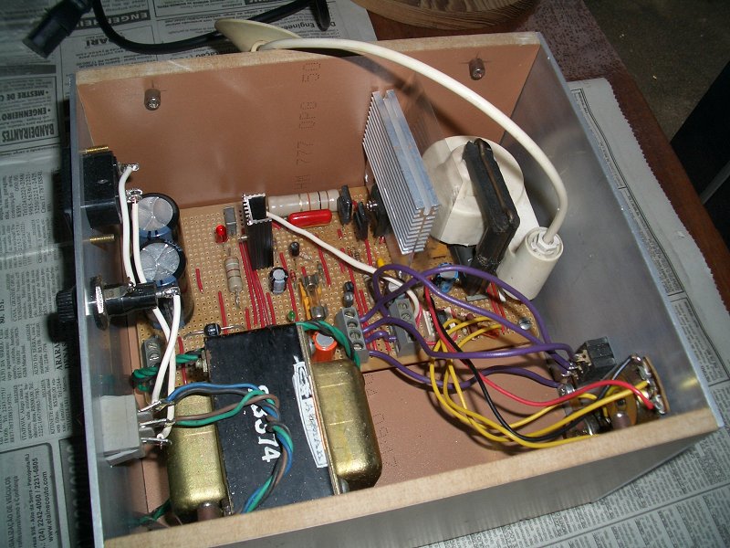
The first attempt used a small flyback from an old computer and a simple driver based on a 555 IC with AC coupling to the driver transistor, with this schematic diagram. It was assembled in a perforated board and put in a box. The circuit has two possible power supply voltages for the flyback, a discrete 12 V voltage regulator, and a 555 astable oscillator where the frequency and the duty cycle can be varied, although not independently. It is similar to other drivers that can be found in the Internet. I tested it by producing sparks between balls.
The spark length between balls is a precise measurement of the available voltage. In these experiments, I put 500 kOhms of resistance (5 1 W 100 kOhms resistors) in series with the output, and a 50 pF Leyden jar across the spark gap. Without the jar, the sparks are weaker an blue or violet. It produces about 20 kV, at a few mA. This circuit had problems with excessive power dissipation in some resistors (R1 and R3) and insufficient base drive for the power transistor when the duty cycle was high with 50 V supply, due to the AC coupling. The small flyback had also a tendency to spark to its core, to the box, and to the heat sink of the power transistor. It also had not enough power to power a "lifter".
The insulation problem was solved by filling the tube where the output cable enters the transformer with silicone glue. The power supply can now power a Jacob's ladder without problems. I could also make the circuit generate enough voltage for a "lifter" (see below) by replacing the snubber network by a simple 4.3 nF 1600 V capacitor:
The second version uses a bigger flyback transformer and a better system to drive the power transistor from the 555, producing a base current in the form of a ramp, following the collector current, that is also a ramp in these circuits. I obtained this by powering the base through an inductor, the primary coil of a transformer, and using a MOSFET to interrupt the base current. A DC connection makes it work uniformly with any duty cycle. A system for recycling the energy stored in the inductor was also implemented, using the secondary coil of the transformer and a fast diode. The 555 was set to produce a square wave with adjustable duty cycle, and a binary array of capacitors was used to set the oscillation frequency. About 5 kHz works better, and it's not useful to be able to change it. This flyback transformer has a capacitor across its output. Shocks from it are quite violent and dangerous.
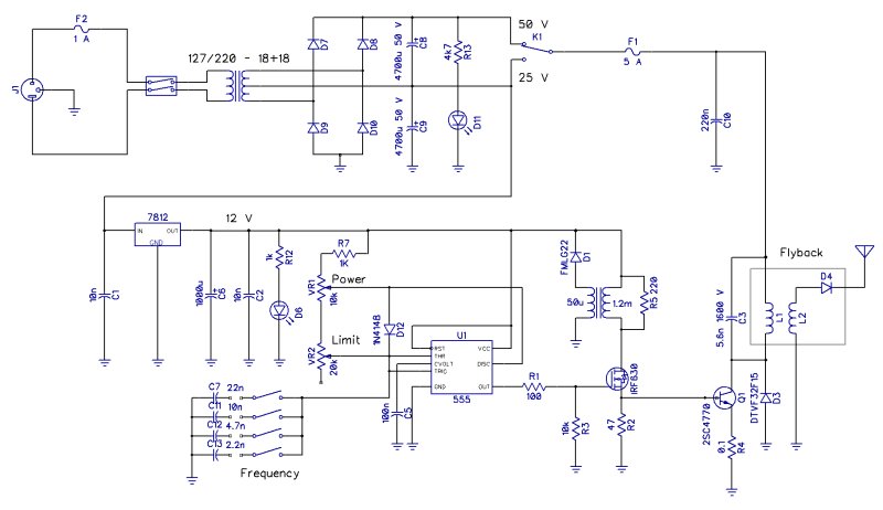
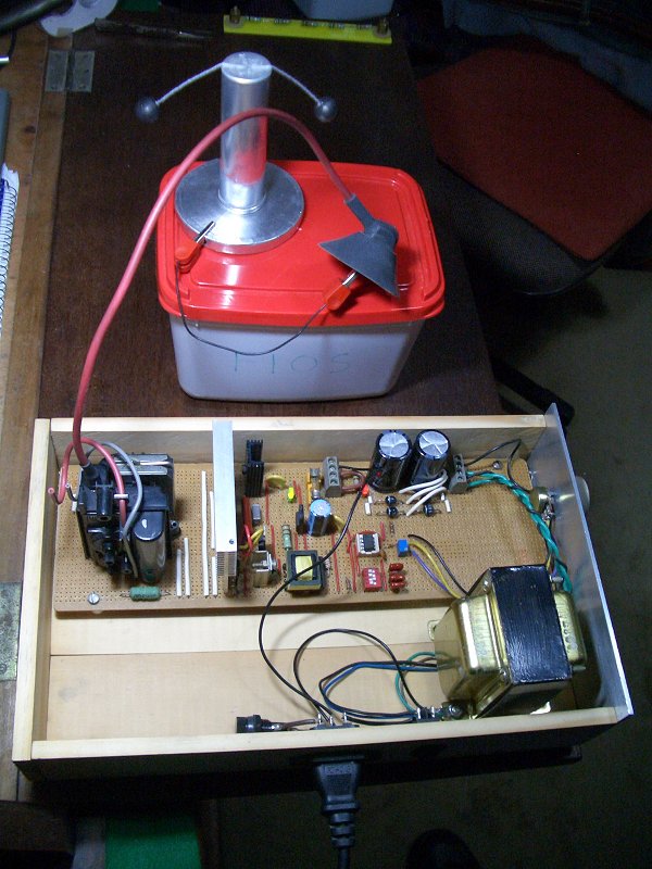
I used an integrated regulator, and a single capacitor as snubber. Combined with the diode across the transistor, the circuit recycles the energy stored in the flyback transformer when the load is light. The driving transformer was simply selected among several salvaged from monitors. It could be bigger, because it almost saturates at the maximum current, but was enough for this use. This driver consumes much less power than the first one, and produces significantly more power. I assembled it in an open box, with more clearance around the flyback. Below it is being tested connected to a ball electrometer: The electrometer is made with two 1.4 cm styrofoam balls painted with China ink, suspended from threads, taped to a metal tube. I estimate about 25 kV at this separation of the balls. A video.
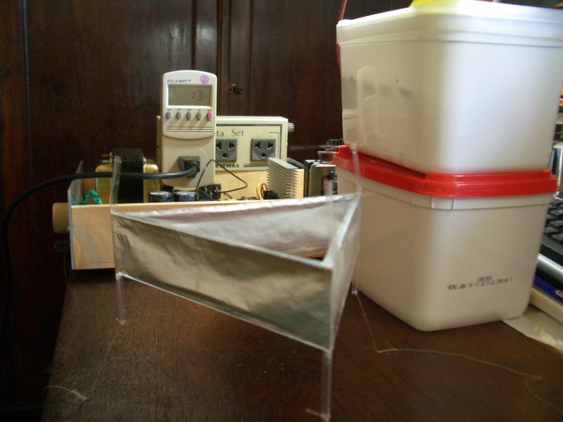
I glued kitchen aluminum foil to the sides of the structure (didn't fold it over the upper beams, as seen in some desingns) with paper glue, and used thin nickel-chrome wire for the corona wires. The sides measure 14 cm, and the total height is 9 cm. It weights a little less than 2 grams. It is connected to the power supply through 500 kOhms of resistance in series with the high-voltage terminal, connected to the corona wires, that are then positive. The resistance is just to prevent disasters. The lower armature is connected to the ground of the power supply. The connections are through thin enameled copper wire. The first power supply just makes it dance, rising only one or two legs. The second supply makes if fly without much trouble (video). I had problems with vibration of the wires, probably caused by 120 Hz ripple in the power supply voltage, but could attenuate it acceptably by tightening the wires a bit. Most of the noise in the video below is due to the vibration. I tried also to tie the centers of the wires with a triangle of sewing line, what also eliminates the vibration, but I had the impression of less power with this. The lifter works better when the power supply is somewhat below the maximum voltage. It produces a lot of ozone, so it must be operated in a well-ventilated place.
After some adjustments in the power supply I could get more reliable results. Video. The whole system consumes just 13 W from the power line, according to a Kill-a-Watt meter. After takeoff, the lifter remains aloft with 10 or 11 W only. The maximum power supply voltage is a bit above 25 kV. The average current for the lifter is about 0.7 mA. There are 5 MOhms of resistance in series with the power supply in the video. 500 kOhms results in no visible difference.
I could also make the lifter work with the first power supply, as said above. Video.
Experiment with a new switching power supply, and a flyback driver similar to the one of the last circuit, in development. The operation is more "solid" with some additional power, and the efficiency is better. Just 10 W from the power line. The power supply was made with components taken from discarded monitors, essentially copying the power supply of a monitor, generating +/- 11 V and 70 V. The flyback driver uses a different oscillator. This is a video showing the system, assembled in a more definitive way. I am still improving the flyback driver.
I found that a significant improvement in the lifter (mentioned in several sites) is to fold the "skirt" over the upper structural beam. This reduces corona there, and eliminates a tendency for vibration of the corona wires. Reduces significantly the ozone generation too. I made a new triangular lifter with 13 cm sides and a square lifter with similar total length (10 cm sides) in this way, leaving 1 cm of extra aluminum foil above the beam (4 cm total width of the foil) and folding the excess over the beam, after gluing the foil in place. Small sections were cut out around the vertical beams. Both weight 1.5 grams. Both lifters performed very well, and could even be powered at the same time, connected in parallel to the power supply. Video.
The vibration of the corona wires is really related to negative corona near them, as shown in this video. If the ground wire attached to the skirt is bent so it passes close to the center of the skirt, this is enough to cause vibration of the corona wire above it. With the ground wire below the skirt there is no vibration. A thin wire ring attached with tape to one of the sides of the skirt causes intense vibration.
The first attempt used a small flyback from an old computer and a simple driver based on a 555 IC with AC coupling to the driver transistor, with this schematic diagram. It was assembled in a perforated board and put in a box. The circuit has two possible power supply voltages for the flyback, a discrete 12 V voltage regulator, and a 555 astable oscillator where the frequency and the duty cycle can be varied, although not independently. It is similar to other drivers that can be found in the Internet. I tested it by producing sparks between balls.
The spark length between balls is a precise measurement of the available voltage. In these experiments, I put 500 kOhms of resistance (5 1 W 100 kOhms resistors) in series with the output, and a 50 pF Leyden jar across the spark gap. Without the jar, the sparks are weaker an blue or violet. It produces about 20 kV, at a few mA. This circuit had problems with excessive power dissipation in some resistors (R1 and R3) and insufficient base drive for the power transistor when the duty cycle was high with 50 V supply, due to the AC coupling. The small flyback had also a tendency to spark to its core, to the box, and to the heat sink of the power transistor. It also had not enough power to power a "lifter".
The insulation problem was solved by filling the tube where the output cable enters the transformer with silicone glue. The power supply can now power a Jacob's ladder without problems. I could also make the circuit generate enough voltage for a "lifter" (see below) by replacing the snubber network by a simple 4.3 nF 1600 V capacitor:
The second version uses a bigger flyback transformer and a better system to drive the power transistor from the 555, producing a base current in the form of a ramp, following the collector current, that is also a ramp in these circuits. I obtained this by powering the base through an inductor, the primary coil of a transformer, and using a MOSFET to interrupt the base current. A DC connection makes it work uniformly with any duty cycle. A system for recycling the energy stored in the inductor was also implemented, using the secondary coil of the transformer and a fast diode. The 555 was set to produce a square wave with adjustable duty cycle, and a binary array of capacitors was used to set the oscillation frequency. About 5 kHz works better, and it's not useful to be able to change it. This flyback transformer has a capacitor across its output. Shocks from it are quite violent and dangerous.
I used an integrated regulator, and a single capacitor as snubber. Combined with the diode across the transistor, the circuit recycles the energy stored in the flyback transformer when the load is light. The driving transformer was simply selected among several salvaged from monitors. It could be bigger, because it almost saturates at the maximum current, but was enough for this use. This driver consumes much less power than the first one, and produces significantly more power. I assembled it in an open box, with more clearance around the flyback. Below it is being tested connected to a ball electrometer: The electrometer is made with two 1.4 cm styrofoam balls painted with China ink, suspended from threads, taped to a metal tube. I estimate about 25 kV at this separation of the balls. A video.
A Lifter
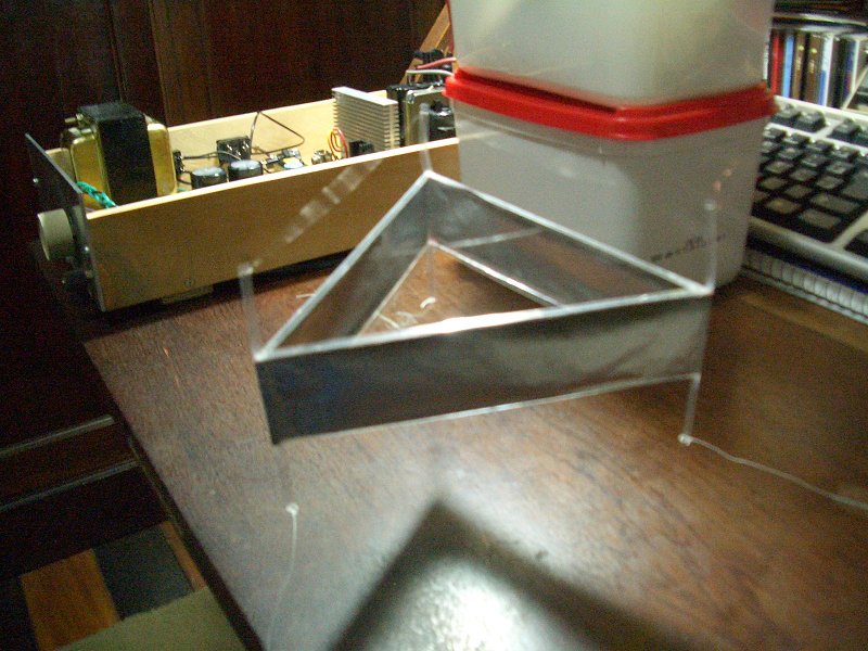
I made a "lifter" to be operated by these power supplies. These curions devices lift their own weight from the ground using ionic wind. It has the conventional triangular structure, that I made with "L beams" made with transparency plastic foil glued with cyanoacrilate glue. The structure made in this way is light and highly insulating.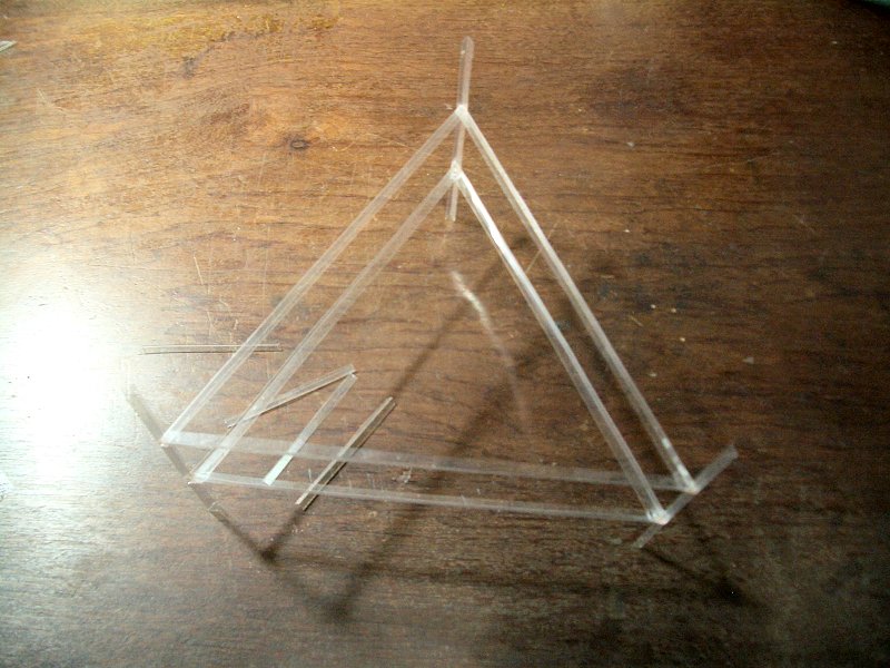
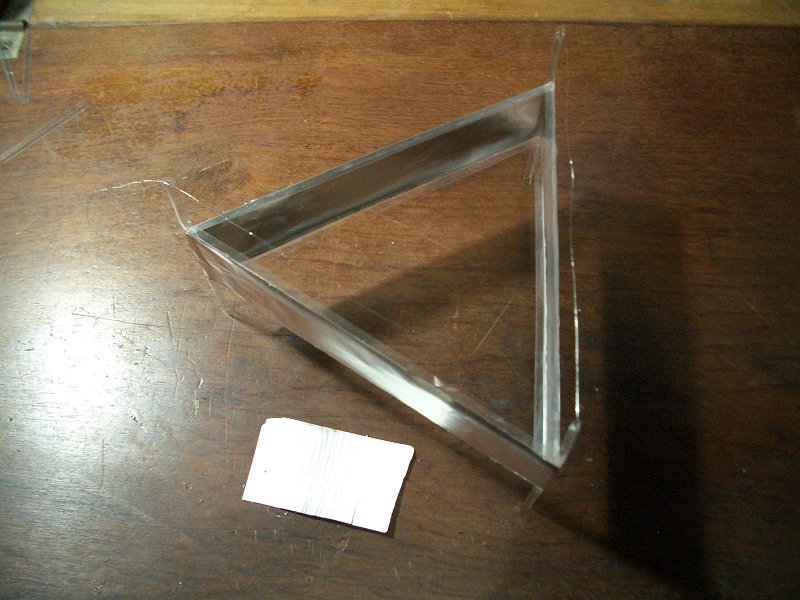
I glued kitchen aluminum foil to the sides of the structure (didn't fold it over the upper beams, as seen in some desingns) with paper glue, and used thin nickel-chrome wire for the corona wires. The sides measure 14 cm, and the total height is 9 cm. It weights a little less than 2 grams. It is connected to the power supply through 500 kOhms of resistance in series with the high-voltage terminal, connected to the corona wires, that are then positive. The resistance is just to prevent disasters. The lower armature is connected to the ground of the power supply. The connections are through thin enameled copper wire. The first power supply just makes it dance, rising only one or two legs. The second supply makes if fly without much trouble (video). I had problems with vibration of the wires, probably caused by 120 Hz ripple in the power supply voltage, but could attenuate it acceptably by tightening the wires a bit. Most of the noise in the video below is due to the vibration. I tried also to tie the centers of the wires with a triangle of sewing line, what also eliminates the vibration, but I had the impression of less power with this. The lifter works better when the power supply is somewhat below the maximum voltage. It produces a lot of ozone, so it must be operated in a well-ventilated place.
After some adjustments in the power supply I could get more reliable results. Video. The whole system consumes just 13 W from the power line, according to a Kill-a-Watt meter. After takeoff, the lifter remains aloft with 10 or 11 W only. The maximum power supply voltage is a bit above 25 kV. The average current for the lifter is about 0.7 mA. There are 5 MOhms of resistance in series with the power supply in the video. 500 kOhms results in no visible difference.
I could also make the lifter work with the first power supply, as said above. Video.
Experiment with a new switching power supply, and a flyback driver similar to the one of the last circuit, in development. The operation is more "solid" with some additional power, and the efficiency is better. Just 10 W from the power line. The power supply was made with components taken from discarded monitors, essentially copying the power supply of a monitor, generating +/- 11 V and 70 V. The flyback driver uses a different oscillator. This is a video showing the system, assembled in a more definitive way. I am still improving the flyback driver.
I found that a significant improvement in the lifter (mentioned in several sites) is to fold the "skirt" over the upper structural beam. This reduces corona there, and eliminates a tendency for vibration of the corona wires. Reduces significantly the ozone generation too. I made a new triangular lifter with 13 cm sides and a square lifter with similar total length (10 cm sides) in this way, leaving 1 cm of extra aluminum foil above the beam (4 cm total width of the foil) and folding the excess over the beam, after gluing the foil in place. Small sections were cut out around the vertical beams. Both weight 1.5 grams. Both lifters performed very well, and could even be powered at the same time, connected in parallel to the power supply. Video.
The vibration of the corona wires is really related to negative corona near them, as shown in this video. If the ground wire attached to the skirt is bent so it passes close to the center of the skirt, this is enough to cause vibration of the corona wire above it. With the ground wire below the skirt there is no vibration. A thin wire ring attached with tape to one of the sides of the skirt causes intense vibration.