 |
 |
Restoration of a Ducretet & Roger Wimshurst machine
|
|
History and original state
When the museum of the Engineering School of the Federal University of Rio de Janeiro was organized, by 1977, I was in the electronic engineering course, and had my attention called by a large old Wimshurst machine that was among the instruments being prepared for the museum. It was in bad shape, with the disks broken and some parts missing, but was a beautiful instrument. Some years later, I saw it on display at the old building of the engineering school at the Largo de S. Francisco, in downtown Rio de Janeiro. By the middle of 1997, in a visit to the museum, I asked about that machine, saying that I could try to restore it, and left with the personnel there a picture taken from an old book (1890) showing a similar machine. Eventually we found the machine, split in several parts in a deposit where some extra instruments were kept.
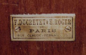
The machine has a brass label in the frontal upright support saying: "F. DUCRETET & E. ROGER - PARIS - RUE CLAUDE-BERNARD, 75" [ref.]. The glass disks were broken in pieces, as one of the bakelite insulating handles of the terminals. One Leyden jar, the driving cords, and one of the balls of the spark gap were missing. All the brass parts, originally lacquered, were heavily oxidized. The wood parts were in good condition, except for a scratch in one of the uprights, and some insect holes in the base. The remaining Leyden jar was without the tin metal plates and with the connectors of both plates missing. Of the neutralizer brushes there were just remains of very thin wires. I restored the machine during October and November in 1997. My intentions were to restore the original appearance and the functionality of the machine, without necessarily using the same original materials and techniques. I would keep the original parts unmodified, and make new parts for the missing ones.
Restoration
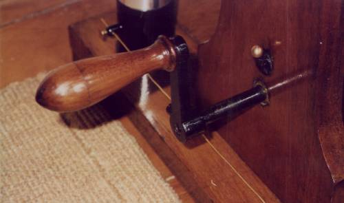
I started the restoration by cleaning everything. The black oxide covering most of the brass parts was easy to remove with muriatic acid (maybe some other acid would be better. The muriatic acid leaves a red copper deposit over the oxidized areas). I removed what was left of the lacquering of the brass parts with acetone and steel wool. I didn't try to polish the brass again, as it was too corroded by the oxidation. I just cleaned the parts well, and lacquered them again with shellac varnish. Shellac here is called "goma laca". It is dissolved with alcohol and a little acetone, and applied to the brass with fast touches with a brush, in only one direction, with the parts previously heated over an alcohol flame, to just below the limit where they can be touched. I applied also a new layer of varnish to the wood parts, after cleaning the surfaces and applying some insecticide. Some metal parts were painted black, as the crank, and I repainted them.
I made new disks in clear acrylic, 2.5 mm thick. The diameter of the disks I could obtain from the remaining pieces of the original glass disks as 46.4 cm. The disks were first cut with a saw from square sheets, and cut to perfect round shape by using a special tool that I made. The tool consists of a wood plate with a metal pin where the center of the disk is precisely fixed, and a support that holds an electric tool with a milling point. Both parts are solidly fixed to a table with clamps. The disk is mounted in the pin, and have its border moved against the grinder, that enters the disk border slightly. The clamp fixing the wood plate with the disk is then tightened, and the disk is slowly rotated while the milling tool cuts the border to a perfect circle. The sectors of the original disks were made of thin tin foil, and had a long crest in the middle filled with wax on the underside. The idea was probably to avoid contact of the neutralizer brushes with the varnished glass disks. That implementation, however, was not good. All the remaining sectors in the broken disk pieces were damaged due to accidental contact with the charge collector points. Apparently, the original disks were very irregular and somewhat warped, what gave little lifetime for the machine. This I could conclude by the absence of visible wear at the bearings of the upper or lower axis (brass tubes running over steel bars). While mounting the sectors, I tested the machine operation with 10 and 20 sectors in each disk. With 10 sectors, it was necessary to start it as a sectorless machine to get it working (spraying charge in the disks, at positions opposite to the neutralizers). With 20 sectors, it was enough to apply some charge to one of the terminals to start it. With the full 40 sectors per disk, it become self-starting.
I made the new sectors out of thick (0.4 mm) aluminum foil with the same shape of the original sectors. The crests were made by running a steel ball over the aluminum foil, making pressure with a wood block, while fixing the foil over an acrylic piece where I cut an elongated hole with the shape of the crests. After making the crests, I cut the sectors out with scissors. It was a lot of work making the 80 sectors... These sectors are hard enough to survive eventual touches to the collectors, but the precision of the new disks turns this almost impossible, unless the machine is incorrectly assembled. I glued the sectors to the disks with contact glue (I should have searched for a transparent glue, that would improve the appearance of the sectors as seen from the underside through the transparent disks).
The broken bakelite handle I replaced by another, made from a black nylon block turned on a lathe. With a layer of varnish the appearance is perfect, and the insulation too. The missing terminal ball I replaced by a solid brass ball cut in a lathe. The terminal balls of this machine are simply inserted at the tip of the terminals with a slight pressure. The remaining original ball is hollow, but I don't know how to make a hollow ball. Possibly they were originally of different sizes, but all the pictures that I found depicting similar machines show identical balls.
I could not find another glass tube similar to the one of the original Leyden jar, a rather irregular tube of greenish glass, with the shape of a test tube. Considering also that the original tube had some bubbles that could lead to a collapse of the insulation if the restored machine ends producing higher voltage that the original, I had two new tubes made by a glass maker, and didn't use the remaining original tube. I made copies of all the parts of the original (somewhat overcomplicated) Leyden jar and completed the missing parts (a connector at the base, a ball at the top terminal, connecting bars to the terminals, and the metal plates) of the original jar. The result were two capacitors with about 90 pF of capacitance each, with insulation good for more than 200 kV.
It was interesting to see that the material used to fix the metal and glass parts together in the supports holding the terminals and in the Leyden jar bases was red sealing wax, easy to apply or remove by heating the parts. There was enough in the base of the remaining Leyden jar to use in the new jar that I made and to repair the terminal supports, that were loose.
The cords that turn the disks I initially made with a round rubber cord, but after some time they started to deteriorate liberating a black dust, and I replaced them by round leather belts of the type used in sewing machines, joined by cutting the extremities at 30 degrees angle and gluing them with cyanoacrylate glue. I eventually had to add steel wire clamps to have strong enough joints.
The neutralizer brushes I made with thin nickel-chrome wire taken from a wire-wound resistor. I used just four wires in each brush, fixed to the holes at the tips of the neutralizer bars with the help of small wood pins and some glue. The bumps in the sectors caused frequent breaks in the the brush wires. I had to use a thicker wire (0.06 mm) than I normally use (0.02 mm), but the brushes still didn't last long. I tried also to use strips of conductive rubber tape, but this caused startup difficulties, unlsess one of the brushes was kept metallic. I then installed brushes made of thin strips of silver foil, that appear to last longer, and were the classical meterial for these brushes.
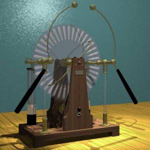
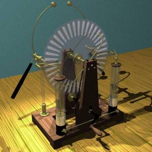
Finally, I applied a layer of carnauba wax everywhere, for protection and improvement of the insulation, specially of the glass supports and Leyden jars. I didn't varnish the glass parts. The rebuilt machine self-starts easily, even in high humidity conditions, producing easily 13 cm sparks even with more than 80% relative humidity. In dryer weather it produced sparks with up to 18 cm. More than this causes sparking through the disk sectors (could also cause sparking directly across the disks, trough the bosses, that are at 9 cm from the charge collectors). The short-circuit current reaches about 40 uA, at 4 turns per second at the crank.
Details of the machine
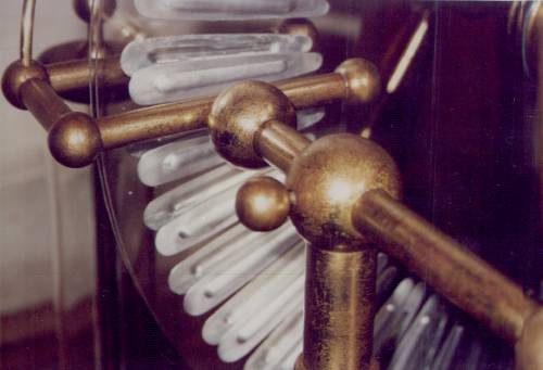
The terminal assemblies are supported by solid glass supports, fixed with sealing wax to brass cups below and above. The lower supports are fixed to the base by screws and hand nuts. Their position can be adjusted to the sides, as the holes in the base are elongated. The upper cups end in large brass balls. These balls are hollow, with thick walls, and have holes, where the brass tubes of the main conductors pass, fixed in place by screws with large spherical heads that pass through the balls. At the inner extremities, the main conductors have balls soldered. These balls have cylindric depressions, where the charge collectors are fixed through screws that have their heads inside the tubes of the main conductors. The charge collectors are brass tubes with balls soldered at each extremity, and with sets of points protruding in the direction of the disks. They are separated in two parts, the back sections having plugs (brass tubes cut in two lengthwise) that fix them in tubes in the front sections, so they can easily be rotated or removed to simplify the mounting of the disks. The long brass bars with the terminal balls are screwed into solid brass balls, where the ebonite handles are also screwed, through short brass bars. These balls have long solid plugs with lengthwise cuts soldered, that are inserted into the main conductor tubes, so the assemblies can be freely rotated, with some friction to hold the terminals in place.
The tall Leyden jars are fixed with sealing wax in brass cups fixed to the wood base by screws and hand nuts identical to the ones of the terminal supports. Normally, the two bases, that are in contact with the outer plates of the capacitors, are electrically interconnected by a brass wire fixed to terminals in the cups. This results in intense bright sparks at the terminals. If the shorting wire is removed, the jars are interconnected through the high resistance of the wood base. Sparks continue to occur, but have their current reduced, producing interesting branching patterns (or just turning them visible) and a characteristic sound. At the outer terminals of the Leyden jars, high-voltage pulses can be extracted at each spark at the main terminals. The Leyden jars can be disconnected by removing the brass bars that connect them to the charge collectors, resting on holes in brass balls. In all the old drawings that I found, these bars connect to the inner terminal balls of the charge collectors at the back of the machine. In this machine, however, the connections are to the outer balls.
The upright supports fit into slots in the base, and are fixed to it with two long wood screws each (at least, this was what I used, since the screws were missing). I added wood bars below the base, where the heads of these screws rest, as reinforcements to the insect-eaten base. The uprights hold the bearings for the steel driving axis, that are brass parts firmly screwed to them. The bearings have brass pieces mounted above them, with little screws with spherical heads closing apertures where lubricant oil is applied. The steel axis for the disks is fixed to the uprights by two wood blocks and four screws, that screw into threads in four brass cylinders embedded in the uprights.
The disks have circular holes in the center that rest in cylindrical projections of the bosses, and are fixed to the them by two cloth rings and circular brass plates, fixed with three screws each, that lay between the disks. At the center of the upper axis there is a fixed brass ring that keeps the disks separated. The bosses are in solid brass, and have holes where lubricant oil can be applied. They have also little engravings saying DUCRETET & ROGER - PARIS. At the front extremity of the upper axis, a headless screw inserts into a hole in the upright, what impedes the rotation of the axis and marks the correct position for the disks.
The neutralizer bars are screwed into brass rings that are fixed with pressure screws to the upper axis, and also impede the sliding of the bosses over the axis. The brushes are fixed in holes at the other extremities, that have also longitudinal slits. Brass pieces screw over threads there, fixing the brushes in place by pressure through the slits.
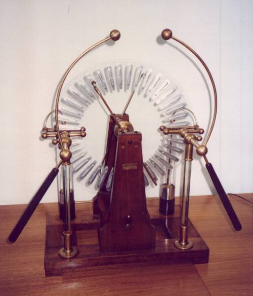
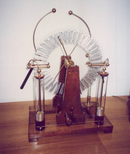
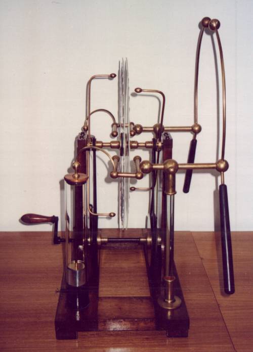
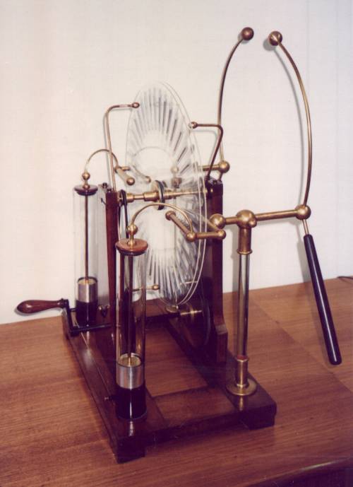
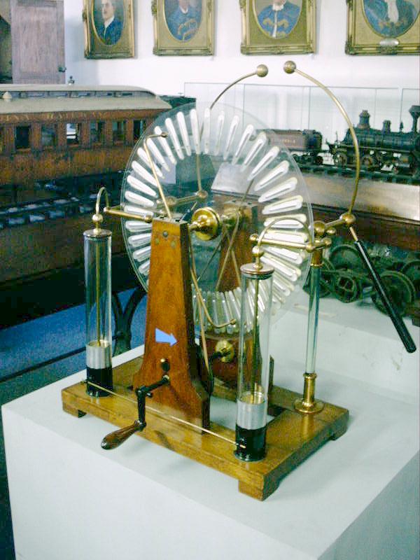
The complete machine, in front view, back view, side view, and another view.
Producing long sparks in a
demonstration.
The machine after a cleaning and protective relacquering in March
2002. Front view, back
view.
Created: 1997.
Last update: 13 April 2002
By Antonio Carlos M. de Queiroz
Return to Electrostatic Machines.